
Testing Equipments Supplier
ISO9001: 2015 Certified
Views: 2 Author: Site Editor Publish Time: 2026-08-25 Origin: Site


Large infrastructure projects demand high-resolution subsurface mapping to prevent utility strikes and ensure structural integrity. Traditional localized locating tools fall short when you need to survey miles of highway or expansive airport runways. Ground penetrating radar provides the highest resolution surface geophysical method available, turning invisible underground zones into actionable data. Selecting the wrong equipment introduces severe operational risks. Deploying a small unit for a massive highway project creates crippling bottlenecks. Conversely, utilizing a massive array for a confined urban site results in wasted logistical effort and severe maneuverability issues.
The choice between a gpr array system and a portable GPR alters project execution. This decision hinges on site accessibility, required data density, collection speed, and your capacity for complex post-processing. We will break down the technical divergence between these two approaches to optimize field operations.
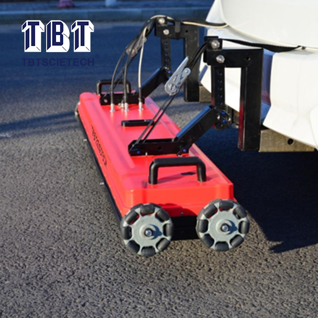
Deployment Scale: Portable GPR units are optimized for rapid deployment, real-time markouts, and confined spaces, whereas GPR array systems are designed for high-speed, large-scale data acquisition.
Data Resolution and Output: Arrays provide dense, multi-channel data for true 3D subsurface modeling; portable units typically rely on single or dual-frequency 2D radargrams, requiring manual grid interpolation for 3D imaging.
Operational Workflow: Portable systems allow for immediate on-site decision-making. Array systems require significant post-processing by trained technicians using specialized software.
Cost vs. Efficiency: While a GPR array system requires a substantially higher initial investment, it drastically reduces field labor hours on expansive sites compared to traditional push-cart methods.
Table of Contents
Evaluating ground penetrating radar equipment requires a rigorous audit of project requirements before any hardware hits the dirt. Different subsurface investigations demand entirely different data collection methodologies. Utility locating focuses on identifying the specific linear alignment and depth of buried pipes or cables. Pavement inspection requires continuous, high-resolution data to measure layer thickness and detect subsurface voids. Archaeological mapping demands meticulous, high-density grids to identify subtle soil disturbances and buried structures.
Conducting a proper site audit involves several mandatory steps to ensure you deploy the correct technology:
Define the primary subsurface target, noting expected depth and material composition.
Assess the total survey area in square feet or linear miles to calculate required field hours.
Identify surface obstructions, traffic conditions, and terrain roughness that might impede movement.
Determine the required deliverable format, ranging from physical field marks to fully integrated 3D CAD models.
Evaluate the soil conditions, specifically looking for high-conductivity clay or saturated environments that attenuate radar signals.
Site constraints heavily dictate equipment selection. The physical environment imposes strict limitations on what hardware can operate within the project footprint. High-volume traffic flow on interstate highways makes slow-moving pedestrian surveys dangerous and logistically complex. Terrain roughness plays a major role. Highly uneven ground, dense vegetation, or steep embankments restrict the use of vehicle-towed systems. Indoor environments present their own challenges. Concrete slab scanning inside active commercial buildings requires compact equipment capable of navigating tight corridors, doorways, and structural columns without disrupting daily operations.
Deliverable requirements determine the necessary data density and processing capabilities. Many localized excavation projects simply require paint-on-the-ground markouts. Field technicians interpret data in real-time and physically mark utility locations on the surface. Modern infrastructure design frequently requires comprehensive 3D CAD or BIM integration. These advanced deliverables demand dense, georeferenced data sets processed into accurate three-dimensional point clouds. Matching the equipment's output capabilities to the final deliverable ensures project success.
Portable systems represent the industry standard for localized subsurface investigations. This category encompasses traditional push carts and small handheld devices. System architecture typically relies on single or dual-frequency antenna configurations. Push carts generally house antennas ranging from 250 MHz to 1000 MHz. This balances penetration depth with target resolution. Small handheld devices utilize much higher frequencies, often between 1000 MHz and 3000 MHz. These high-frequency handhelds provide exceptional resolution for concrete scanning and rebar detection. They suffer from severe depth limitations compared to full-size push carts.
Operational agility stands as the primary advantage of a portable GPR. These units allow for rapid setup. You can transition from the transport vehicle to active scanning in under ten minutes. Their compact footprint enables exceptional maneuverability in tight urban environments, crowded sidewalks, and complex industrial facilities. A single operator can easily transport, assemble, and deploy the equipment. You do not need specialized towing vehicles or heavy lifting apparatus. This agility makes portable systems highly responsive to emergency utility markout requests.
The mechanics of a push cart rely on an encoder wheel that triggers radar pulses based on distance traveled rather than time. This ensures consistent data collection regardless of how fast the operator walks. Real-time interpretation capabilities empower operators to make immediate on-site decisions. As the antenna moves across the surface, the control unit displays two-way travel time data as a continuous 2D radargram. Skilled technicians analyze these hyperbolic reflections on the fly. Accurate depth estimation requires on-site wave velocity calibration. Operators achieve this by matching hyperbola shapes to known dielectric constants or by calibrating against a target of known depth. This immediate velocity calibration allows technicians to provide accurate depth readings for site markouts before excavation begins.
Despite their versatility, portable units possess inherent limitations when applied to large-scale mapping. Creating 3D maps with a single-channel portable unit requires highly labor-intensive manual grid scanning. Operators must physically lay out perpendicular grid lines and push the cart precisely along each transect. Pushing a cart over rough terrain for eight hours introduces significant physical strain on the operator. Furthermore, this methodology introduces a massive risk of spatial aliasing. If the spacing between grid lines exceeds the size of the subsurface target, utilities or voids can easily fall between the scanning paths. They remain completely undetected. Manual grid interpolation is inherently slow and prone to human error over large areas.
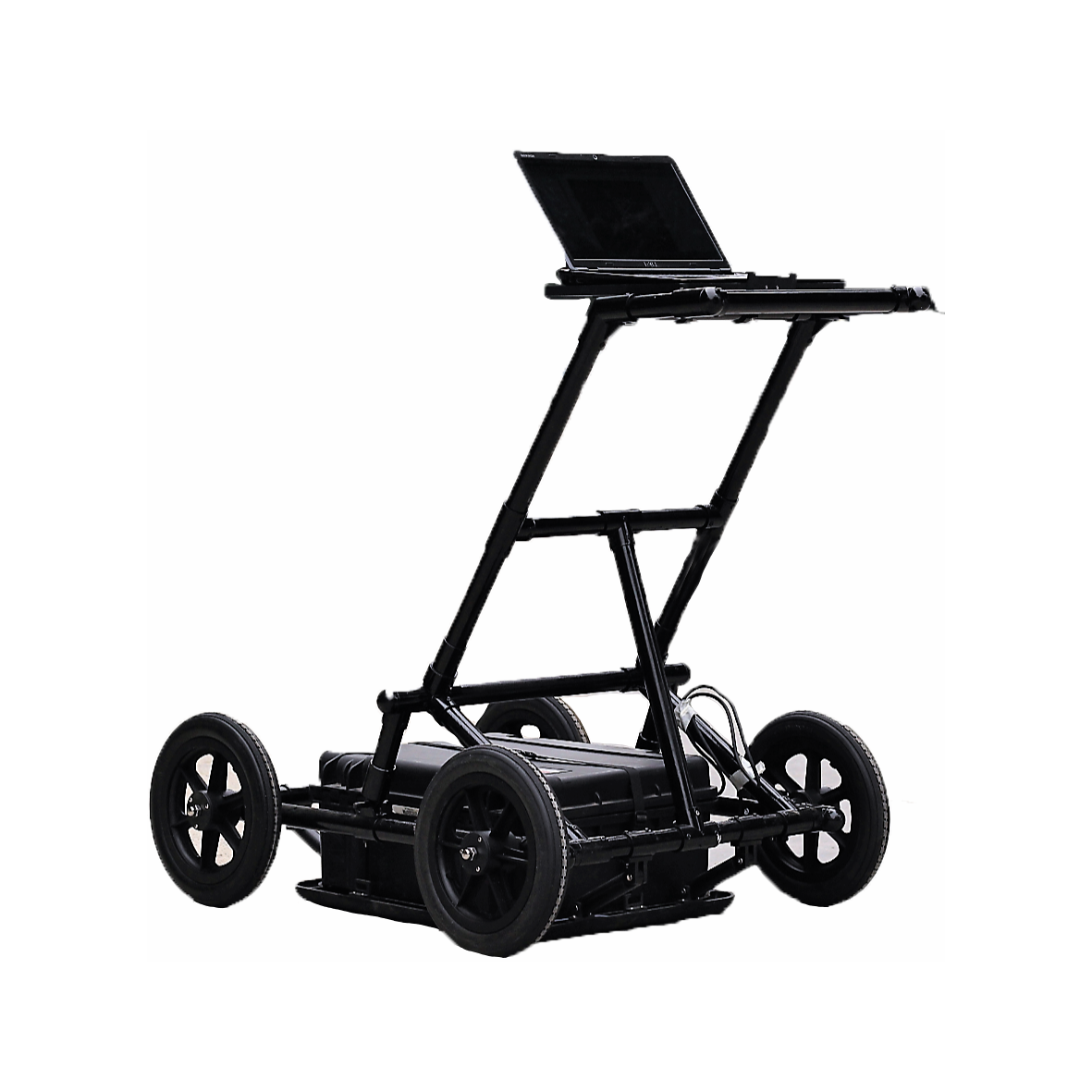
The gpr array system represents a massive leap in subsurface data acquisition technology. These systems utilize a vehicle-towed, multi-channel architecture. Instead of a single antenna, an array houses dozens of closely spaced antenna elements within a single rigid housing. These configurations often employ stepped-frequency continuous wave (SFCW) technology. Instead of firing a single broad pulse, SFCW sweeps through a wide range of frequencies continuously. The array transmits these signals across a wide physical footprint. It captures a massive volume of subsurface data simultaneously. This architecture transforms data collection from a linear process into a broad, sweeping acquisition method.
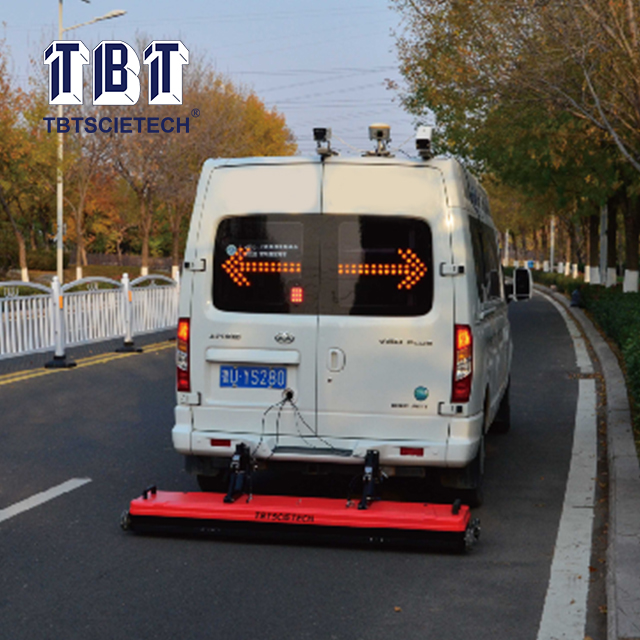
High-speed data acquisition fundamentally changes how large infrastructure projects are surveyed. Array systems can be deployed at standard highway speeds. This capability eliminates the need for extensive lane closures, rolling roadblocks, and heavy traffic control measures. Surveying miles of interstate highway or expansive airport runways becomes a matter of hours rather than weeks. Minimizing traffic disruption drastically improves safety for both the survey crew and the general public. The ability to collect data at the speed of traffic provides a massive operational advantage for transportation departments and large engineering firms.
True 3D data density separates array systems from traditional portable units. Because the antenna elements are spaced mere centimeters apart, the system captures a continuous, high-resolution 3D swath in a single pass. This dense data collection eliminates the spatial aliasing risks associated with manual grid scanning. The resulting data set provides superior lateral and vertical resolution. Analysts can slice the 3D data volume at specific depth intervals. This reveals complex utility networks, structural anomalies, and geological variations with unprecedented clarity. To achieve this, arrays rely heavily on sub-centimeter positioning. They integrate directly with RTK GPS networks or robotic total stations to georeference every single radar pulse.
Array systems carry distinct inherent limitations. Their massive physical footprint requires vehicle access and clear, unobstructed pathways. They cannot navigate highly confined urban spaces, narrow pedestrian walkways, or building interiors. The rigid housing of the array requires relatively flat surfaces to maintain proper ground coupling. Highly uneven terrain, deep ruts, or heavy vegetation will severely degrade data quality or physically damage the equipment. These systems are purpose-built for open, accessible environments. They struggle in constrained or rugged topographies.
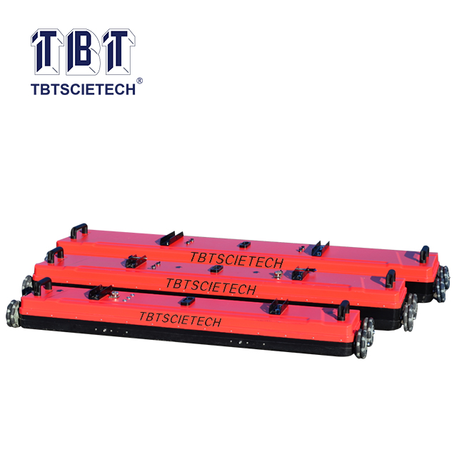
Collection rates differ drastically between the two methodologies. A walking-speed portable unit typically covers roughly 2 to 3 miles of linear scanning per day. This assumes ideal conditions and minimal surface obstructions. This slow pace works perfectly for localized trenching paths or intersection markouts. In stark contrast, a vehicle-mounted array system collects data at speeds exceeding 50 miles per hour. Operators can survey hundreds of lane miles in a single deployment.
Operational Metric | Portable GPR | GPR Array System |
|---|---|---|
Average Collection Speed | 1 to 3 mph (walking pace) | 15 to 60 mph (vehicle towed) |
Daily Coverage Potential | 2 to 5 linear miles | 50 to 200+ linear miles |
Traffic Control Required | High (lane closures, flaggers) | Minimal (moves with traffic flow) |
Data Density Output | Low to Medium (2D lines) | Ultra-High (Continuous 3D swath) |
Positioning Integration | Basic GPS or local grid | RTK GPS or Robotic Total Station |
This massive disparity in collection speed directly impacts project timelines. For large-scale utility mapping across a sprawling military base or comprehensive bridge deck inspections across a highway network, manual scanning introduces unacceptable delays. The array system compresses the data acquisition phase. Engineering teams proceed with design and analysis much earlier in the project lifecycle. Mobilizing a vehicle-towed array for a quarter-acre parking lot survey remains highly inefficient and unnecessary.
Antenna frequency choices dictate the fundamental trade-off between penetration depth and spatial resolution. Lower frequencies penetrate deeper into the earth but lack the resolution to detect small targets. Higher frequencies provide crystal-clear resolution for shallow targets but attenuate rapidly in the soil. The Fresnel zone dictates that the radar footprint expands as the signal travels deeper, naturally reducing resolution at depth. Portable systems typically force operators to choose a single frequency for a survey. Alternatively, they perform multiple passes with different antennas to capture both shallow and deep data.
Array systems overcome this limitation by utilizing multiple frequencies or stepped-frequency technology simultaneously. The array maps both shallow rebar networks and deep utility mains in a single pass without compromising resolution at either depth. Both systems require accurate velocity calibration to ensure precise depth measurements. Arrays often capture enough overlapping data to allow processing software to automatically calculate wave velocities across varying soil conditions. Portable systems rely heavily on the operator's manual hyperbola fitting in the field.
The physical footprint of the equipment dictates where it can be deployed. Push-cart systems excel in pedestrian zones, narrow sidewalks, and building interiors. You can easily lift them over curbs, maneuver around parked cars, and push them through standard commercial doorways. This high degree of maneuverability makes them indispensable for urban utility locating and structural concrete scanning.
Deployment logistics for an array system are significantly more complex. These systems require dedicated towing setups. This involves customized hitches, specialized mounting hardware, and heavy-duty suspension modifications to the tow vehicle. You cannot transport them in the trunk of a standard sedan. The vehicle requirements restrict array deployment to areas with established roadways or highly graded surfaces. If a project requires scanning behind a building, across a landscaped berm, or inside a facility, the array system is entirely unsuitable.
Evaluating hardware acquisition requires analyzing the scale of deployment against long-term operational efficiency. Standard portable units represent a highly accessible equipment tier. Their streamlined architecture allows organizations to equip multiple field crews simultaneously. This maximizes geographic coverage for localized daily dispatch operations. Multi-channel array systems demand a premium resource allocation. The complexity of housing dozens of antennas, integrating high-speed positioning systems, and synchronizing massive data streams requires a substantial commitment of logistical resources.
Organizations must evaluate deployment based strictly on labor savings and field efficiency. The heavy initial equipment allocation for an array system is offset by the drastic reduction in field hours required for large projects. A highway survey that might require a four-person crew working for three weeks with push carts can be completed by a two-person crew in a single night with a vehicle-towed array. For engineering firms consistently winning large-scale infrastructure contracts, this massive reduction in field labor rapidly justifies the hardware allocation.
The operational workflow diverges significantly after the data is collected. The portable workflow focuses heavily on real-time interpretation. For standard utility locating, post-processing needs are minimal or entirely non-existent. The technician marks the ground, generates a basic field report, and the job is complete. This streamlined workflow requires minimal office support. Field crews move rapidly from one site to the next.
The array system workflow operates on an entirely different paradigm. These systems generate massive volumes of raw data that cannot be fully interpreted in real-time. This necessitates advanced 3D processing software and high-performance computing hardware. The workflow transitions from field-based labor to office-based data analysis. Trained geophysicists or data analysts must execute a rigorous processing sequence. This includes zero-time correction, background removal, bandpass filtering, migration, and time-depth conversion. They filter, migrate, and interpret the 3D point clouds to extract actionable CAD or BIM deliverables. Organizations deploying arrays must allocate significant resources to software licensing, data storage, and specialized personnel.
Deploying advanced geophysical equipment introduces specific implementation risks that you must manage proactively.
Operator Skill Gap: The transition from interpreting 2D hyperbolic reflections on a portable screen to processing complex 3D array point-clouds requires specialized geophysics training. Field technicians who excel at push-cart markouts may struggle with advanced software migration and slice analysis. Invest heavily in vendor-provided training programs. Hire dedicated office-based data analysts to handle the complex processing workflow.
Environmental Limitations: Both systems are strictly bound by the laws of physics. Highly conductive soils, such as saturated heavy clays, rapidly attenuate radar signals. This renders both portable and array systems ineffective at depth. Conduct soil conductivity tests or review geological maps prior to deploying expensive array systems. Always supplement radar surveys with electromagnetic locators to ensure comprehensive utility detection in poor soil conditions.
Data Overload: Multi-channel array systems generate massive file sizes. They often accumulate hundreds of gigabytes in a single shift. This volume of data can easily overwhelm standard IT infrastructure, causing severe bottlenecks in data transfer and storage. Establish robust data management protocols before deployment. Utilize high-speed solid-state drives for field transfers. Implement secure network-attached storage solutions. Ensure office workstations possess the necessary RAM and processing power to handle massive 3D data volumes.
Audit your historical project data to determine the exact percentage of large-scale mapping jobs versus localized utility markouts.
Evaluate your current internal IT infrastructure to confirm it can support massive 3D data storage and processing requirements.
Request comprehensive field demonstrations of both systems on a known test site to directly compare data output and workflow complexity.
Develop a hybrid deployment strategy utilizing array systems for macro-level mapping and portable units for localized anomaly verification.
For organizations evaluating professional testing and surveying equipment for infrastructure projects, TBT provides equipment solutions designed to support a range of engineering and testing applications. With experience serving infrastructure and engineering projects, TBT can help customers evaluate suitable equipment solutions based on specific testing requirements, project environments, and operational needs.
A: Maximum depth depends entirely on soil conductivity and antenna frequency. Lower frequency portable antennas can penetrate up to 15 feet in ideal, resistive soils. Array systems using stepped-frequency technology achieve similar or slightly deeper penetration while maintaining high resolution for shallow targets. Both systems fail at shallow depths in highly conductive clay.
A: Small handheld systems utilize very high frequencies, typically between 1000 MHz and 3000 MHz. Because high-frequency signals attenuate rapidly, their effective depth range is generally limited to 12 to 24 inches. They are specifically designed for high-resolution scanning of concrete slabs to locate rebar, post-tension cables, and shallow conduits.
A: Yes, array systems are excellent for mapping utility networks. However, they are highly inefficient for simple, single-point utility markouts. Arrays are best utilized when a comprehensive 3D map of all subsurface utilities across a large area is required for engineering design, rather than marking a single trench line.
A: Vehicle-mounted arrays collect data exponentially faster than push carts. A pedestrian operator might cover 2 to 3 linear miles in a full day. An array towed behind a vehicle collects dense 3D data at highway speeds, easily covering 50 to 100 lane miles in a single shift without lane closures.
A: Yes. Unlike portable units that allow for real-time 2D interpretation on the screen, array systems generate massive volumes of 3D data. You must use specialized, vendor-specific or advanced geophysical processing software to filter, migrate, and interpret the data into actionable 3D point clouds or CAD models.
A: Yes, portable systems can create 3D maps, but the process is highly labor-intensive. Operators must manually push the cart over a precise, tightly spaced perpendicular grid. The software then interpolates these 2D slices into a 3D volume. This manual method is slow and carries a higher risk of missing targets.
A: Both systems rely on electromagnetic waves, making them highly susceptible to soil conditions. Conductive soils like wet clay absorb the radar signal, severely limiting depth penetration. Accurate depth measurement in either system requires precise wave velocity calibration to account for the specific dielectric properties of the site's soil.


